Building a Commodore 64 - Part IX - (BMC64 case mounting)
Original controllers and keyboard solutions in place, now I needed to figure out how to fit all of it in an original case. My main goal was to have the joystick ports in the correct place, and all connectors easy to access from the back of the case.
Option 1 - Tape and glue
The first option would be to take the controller prototype I made, and use some kind of tape and glue to hold the DB9 connectors in the right place. I really didn't want to do that and make some permanent changes to the case. There are also limited screw holes inside a C64 case and there was no where to mount the Raspberry Pi in a way and make the ports accessible on the outside of the case without more tape and glue.
So I would need a different solution.
Option 2 - Custom PCB
If I used a custom PCB, it could be mounted on the original motherboard mounts. The controller ports and power switch could be mounted in the correct place. But, I wasn't going to make my own. Luckily the retro community had several options I could look in to.
The three options I found were:
All of these boards have very similar features. You can connect an original C64 keyboard and have two controller ports, all laid out on a PCB you can screw to the original motherboard mounting holes.
BMC PCB
BMC64 is the project that just keeps on giving. Not only have they made great software for the Raspberry Pi, but they make it possible to connect original controllers, and have a custom PCB to fit it all in the case!
The bad news is you have to order the PCB and components yourself and build it. Even though this would be a fun project I was looking for a ready build board or kit.
C-PIO 64
I found this board the C-PIO64 which seems to tick all the boxes. To be honest I don't know why I didn't try this PCB, I guess I thought the one below was more interesting.
Fascination C64
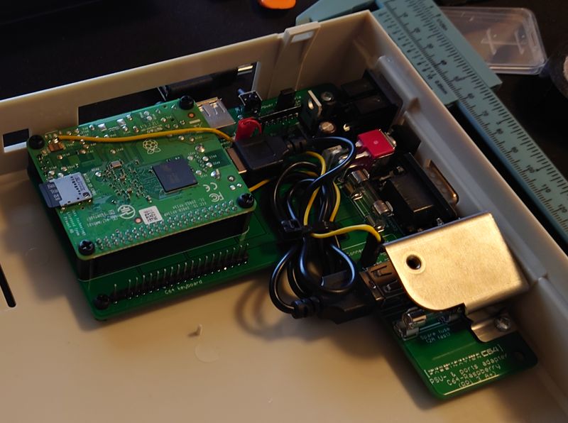
More searching turned up the Fascination C64. Again this ticked all the boxes, and it could even be used with an original C64 power supply, not that I have one. So I promptly ordered one.
Testing
My goals were:
- Fit in the case cleanly
- Connect original C64 keyboard
- Connect original joysticks
- Connect modern wireless controller adapters

The first test fit looked great! Connecting the keyboard and an old Competition Pro also worked great! But that's when the trouble started, the wireless adapters would not power on. I did a bunch of checking to see if I had done something wrong, but nothing would work. So it was time to RTFM!
After looking over the manual I discovered that when the BMC64 is configured to connect both the keyboard and joysticks at the same time, it's not possible to connect the +5V line on pin 7. Pin 7 on the controller ports of original C64's (and the Ultimate 64), is what allows them to power the wireless adapters. Luckily I had already done the work to convert the original C64 keyboard to connect via USB (Part VIII), and configuring BMC64 to just connect the controller ports (GPIO Config 1) would allow me to connect the +5V line... I hoped.
Modifying
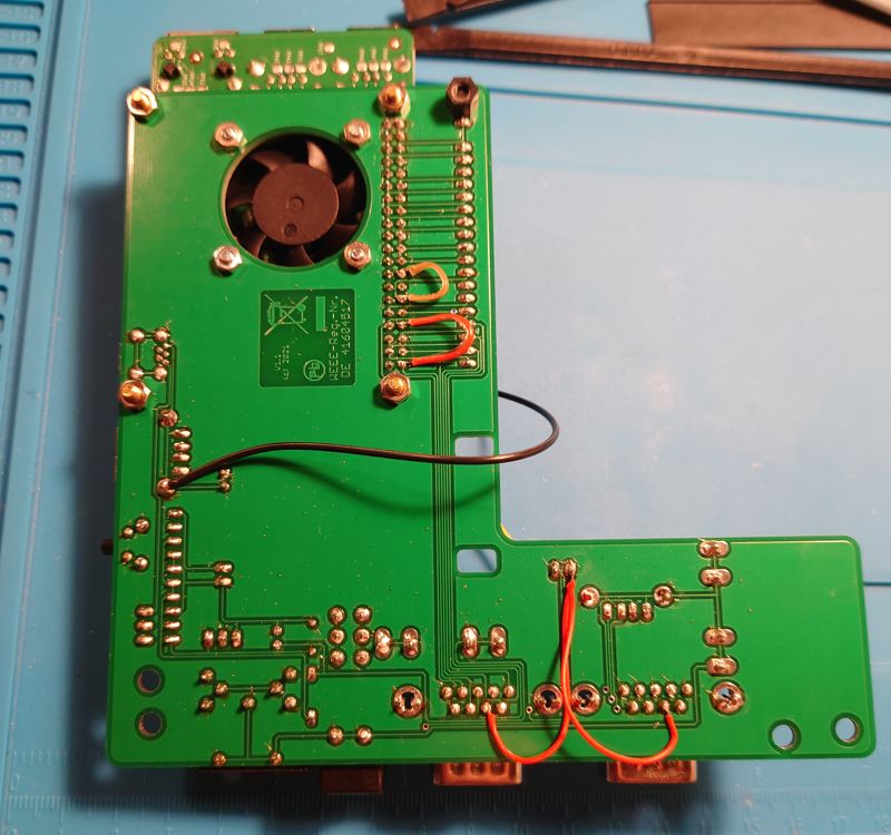
The Fascination C64 was configured for GPIO Config 2, which now wouldn't work, as I needed some power for Pin 7 on the controller ports. I modified the PCB by adding the wiring in the photo below to send power to both pin 7's. I also had to redirect ground to different pins on the Pi header connector on the Fascination C64.

The diagram below shows the connections that need to be made between the Raspberry Pi header and the C64 Keyboard header on the Fascination C64.
                  Raspberry Pi                  Fascination C64         Fascination C64
                   Pi3 Header                 C64 Keyboard Header          Pi3 Header
                     1   2                                    1              1   2
                     .___.                         ._.                       .___.
                    -|O O|--2--+5V                 |O|--1                   -|O O|--2--+5V
                    -|O O|--4--+5V                 |O|--2                   -|O O|--4--+5V
                    -|O O|--6--GND                 |O|--3                   -|O O|--6--GND
                    -|O O|-                        |O|--4   Player 1        -|O O|-
Player 1            -|O O|-                        |O|--5 RIGHT             -|O O|-
     UP   GPIO17--11-|O O|-12--GPIO18  DOWN        |O|--6 LEFT              -|O O|-
   LEFT   GPIO27--13-|O O|-14--GND                 |O|--7 DOWN              -|O O|-
  RIGHT   GPIO22--15-|O O|-16--GPIO23  FIRE        |O|--8 UP                -|O O|-
                    -|O O|-                        |O|--9 FIRE              -|O O|-
                    -|O O|-                        |O|-10                   -|O O|-
                    -|O O|-                        |O|-11                   -|O O|-
                    -|O O|-                        |O|-12                   -|O O|-
                    -|O O|-                        |O|-13                   -|O O|-26--GPIO07 <-\
Player 2            -|O O|-                        |O|-14                   -|O O|-             |
     UP   GPIO5---29-|O O|-30--GND                 |O|-15   Player 2        -|O O|-30--GND <----/
   DOWN   GPIO6---31-|O O|-32--GPIO12  LEFT        |O|-16 RIGHT             -|O O|-     Connect jumpers
  RIGHT   GPIO13--33-|O O|-                        |O|-17 LEFT              -|O O|-34--GND <----\
   FIRE   GPIO19--35-|O O|-                        |O|-18 DOWN              -|O O|-             |
                    -|O O|-                        |O|-19 UP                -|O O|-             |
                    -|O O|-                        |O|-20 FIRE              -|O O|-40--GPIO21 <-/
                     '---'                         '-'                       '---'
                    39   40                                   20            39   40
Additional connections:
- PP2 on Fascination C64 to both Pin 7's on the DB9 connectors
- Raspberry Pi Pin 6 GND connect to ground on the Fascination C64
Here's the original wiring diagram
These changes enabled me to connect from the header on the Raspberry Pi to the keyboard header on the Fascination C64 using jumper wires. Connecting like this translates the GPIO Config 1 on the Pi to the GPIO Config 2 the Fascination C64 was expecting. Not connecting the keyboard meant that there was no problem connecting the +5V line. Hopefully this would meet all of my goals!
Note
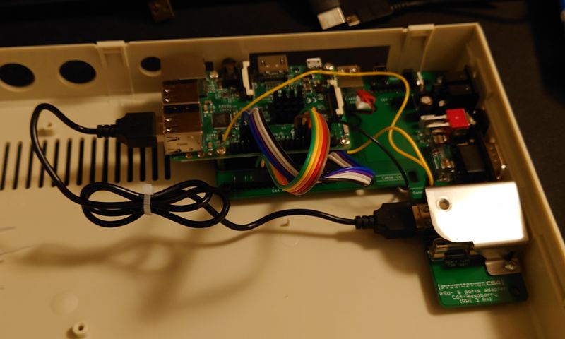
I also removed the Raspberry Pi 3A+ which came with the Fascination C64, and installed a Raspberry Pi 3 instead. I had to first flip it face up, as I could no longer use the Pi header on the Fascination C64.
The finished connections between the Raspberry Pi 3 and Fascination C64 are shown below, note the rainbow jumper cables are the new connections.

Conclusion
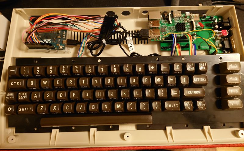
Now all that was left was to connect the keyboard and fit it all in the case

Note
After the picture was taken I added an SD card extension to make it easy to access the SD card from the back of the case without opening it.
So it was a lot more work that expected but the result was well worth it.
Check out the summary for a full parts of the build.
All C64 Posts
- Building a Commodore 64 - Part X - (BMC64 Summary) » 2022-10-16
- Building a Commodore 64 - Part IX - (BMC64 case mounting) » 2022-10-16
- Building a Commodore 64 - Part VIII - (BMC64 Keyboard) » 2022-02-21
- Building a Commodore 64 - Part VII - (BMC64 Controllers) » 2022-02-01
- Building a Commodore 64 - Part VI - (BMC64 Prototype) » 2022-01-30
- Building a Commodore 64 - Part V - (Controllers) » 2022-01-16
- Building a Commodore 64 - Part IV - (Ultimate 64) » 2022-01-13
- Building a Commodore 64 - Part III - (The Keyboard) » 2022-01-03
- Building a Commodore 64 - Part II - (Common parts) » 2022-01-02
- Building a Commodore 64 - Part I - (Why!?!) » 2021-12-31