Building a Commodore 64 - Part VII - (BMC64 Controllers)
The first step of the BMC64 prototype had passed. The Raspberry Pi powered bare metal emulator had booted fast and ran great!
The great thing about the Raspberry Pi is the General Purpose Input/Output (GPIO) headers on the board. This allows you to connect hardware directly to the Pi and interface with it. BMC64 takes full advantage of this and allows connection of both controllers and an original C64 keyboard.
Next stop get original C64 controllers working!
Building Cables
The BMC64 website includes instructions on how to build cables and connect the joysticks to the GPIO pins.
- GPIO Config 1 : Menu Nav Buttons and Joysticks
- Connecting DB9 ports to the GPIO
I initially tried this, but there were a couple of issues
- It's messy, and if a couple of cables slip off you might not remember how to connect them.
- My 8BitDo wireless adapter didn't power on 😕
There had to be a better way.
After some research, I discovered the problem with the wireless adapter was that in the BMC64 schematic they did not connect the VCC (+5V) to pin 7 on the DB9 (pinout), hence no power.
Good news is that the GPIO pins have a couple of +5V outputs so I connected those to pin 7 on the DB9 and then the wireless adapter was up and running!
Now just to clean things up a bit.
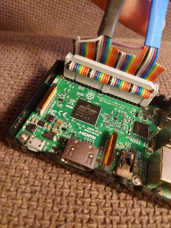
To do that I used a standard 40 pin GPIO ribbon cable. By using a single ribbon cable there was no way to mix up the wiring, and required just one connection both of the joystick ports at once.
Pro tip
Buy the Rainbow variant of the GPIO ribbon cable. Makes it much easier to connect the wires to the right pins.
Parts
- GPIO Female to Female Ribbon Cable - Rainbow!
- DB9 (2x)
Pinout
Below is a handy pinout diagram to explain how to connect the joysticks including the VCC (+5V) line.
                  Pi3 Header                     Joystick (DB9) connectors
                     1   2                             ___. Player 1
                     .___.                            /   |
                    -|O O|--2--+5V                   /  O |-1 UP <-----> GPIO17
                    -|O O|--4--+5V                  | O   |-6 FIRE <---> GPIO23
                    -|O O|-                         |   O |-2 DOWN <---> GPIO18
                    -|O O|-                         | O   |-7 +5V <----> +5V(2)
Player 1            -|O O|-                         |   O |-3 LEFT <---> GPIO27
     UP   GPIO17--11-|O O|-12--GPIO18  DOWN         | O   |-8 GND <----> GND(14)
   LEFT   GPIO27--13-|O O|-14--GND                  |   O |-4 RIGHT <--> GPIO22
  RIGHT   GPIO22--15-|O O|-16--GPIO23  FIRE         | O   |-9
                    -|O O|-                          \  O |-5
                    -|O O|-                           \___|
                    -|O O|-                            ___. Player 2
                    -|O O|-                           /   |
                    -|O O|-                          /  O |-1 UP <-----> GPIO5
Player 2            -|O O|-                         | O   |-6 FIRE <---> GPIO19
     UP   GPIO5---29-|O O|-30--GND                  |   O |-2 DOWN <---> GPIO6
   DOWN   GPIO6---31-|O O|-32--GPIO12  LEFT         | O   |-7 +5V <----> +5V(4)
  RIGHT   GPIO13--33-|O O|-                         |   O |-3 LEFT <---> GPIO12
   FIRE   GPIO19--35-|O O|-                         | O   |-8 GND <----> GND(30)
                    -|O O|-                         |   O |-4 RIGHT <--> GPIO13
                    -|O O|-                         | O   |-9
                     '---'                           \  O |-5
                    39   40                           \___|
Controllers
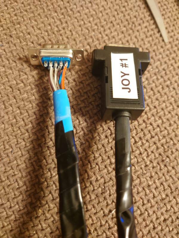
Here is a couple of pictures of the finished prototype Pi3 with the rainbow ribbon cable.


Now you can connect any original joystick, or the more modern wireless adapter with 8BitDo controller. For more details on the controllers jump back to Part V - (Controllers).
Next...
Now I had a Pi3 running BMC64 with original controllers... almost there, just had to replace the USB keyboard with an original C64 keyboard and fit it all in an original case.
All C64 Posts
- Building a Commodore 64 - Part X - (BMC64 Summary) » 2022-10-16
- Building a Commodore 64 - Part IX - (BMC64 case mounting) » 2022-10-16
- Building a Commodore 64 - Part VIII - (BMC64 Keyboard) » 2022-02-21
- Building a Commodore 64 - Part VII - (BMC64 Controllers) » 2022-02-01
- Building a Commodore 64 - Part VI - (BMC64 Prototype) » 2022-01-30
- Building a Commodore 64 - Part V - (Controllers) » 2022-01-16
- Building a Commodore 64 - Part IV - (Ultimate 64) » 2022-01-13
- Building a Commodore 64 - Part III - (The Keyboard) » 2022-01-03
- Building a Commodore 64 - Part II - (Common parts) » 2022-01-02
- Building a Commodore 64 - Part I - (Why!?!) » 2021-12-31